
**All work done by appointment only! Please do not remove your engine without making an appointment! Contact me here**
For Recommended Oil Choices Click Here
Installation
of Carburetor: CT70
This is how you should start to re install your fuel tank & lines to run them through the frame to the carburetor.
You will need some duct tape & about 4-5 feet of twine. Don’t try it with less than 3 1/2 feet or it becomes too difficult.
I like duct tape as opposed to masking tape because duct tape comes off relatively easily. Masking tape is actually too sticky for this procedure.
In the carb kit you received 2 new fuel lines. One short, one long. There are 2 fuel line connections on the tank. The lower line connection on the tank is for the reserve line, which you will see on the carb in these instructions later. The shorter of the 2 fuel lines supplied gets affixed to the reserve connection on the tank. Consequently, the longer one goes to the “on” connection on the tank, which is the higher of the two. Connect the lines accordingly.
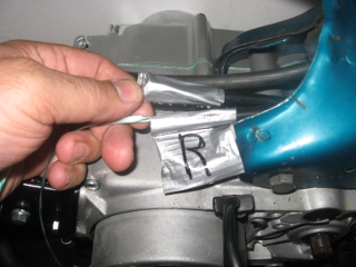
Affix the ends of the twine with the duct tape to each line as shown. A tip is to only take about 2 inches of duct tape to do this. You don’t want to go around 5 times or you’ll never get it off. You only need to hold the twine on very lightly. Also, once i get the hunk of duct tape from the roll, i like to stick it to my clothing a few times to get a coat of lint on. This will help when you go to pull it off later. It makes it a lot easier.
Leave about 1.5 inches of the end of the fuel line showing before the tape, as shown.
For the reserve line, leave a little extra “flag” to denote that is in fact the reserve line, as you will not be able to tell otherwise once you get the 2 lines through the frame. I have the reserve line marked “R” with a marker for this instruction, but it is not necessary.
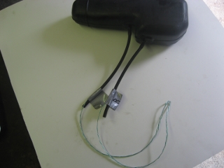
Here we have the single piece of twine with each end attached to the lines.
The twine is there so you can just lay the tank on it’s side on the body of the bike & feed the twine through the frame.
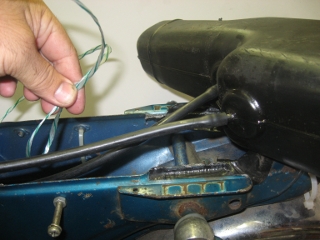
With one hand, feed the twine into the frame & with the other, pull it through.
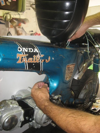
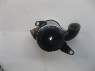
Now that you have the lines through, you can install the airbox. You will notice that the airbox has a rubber boot that fits up into this cavity in the frame. That boot must remain intact with it’s rubber insert in place.
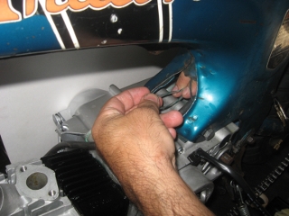
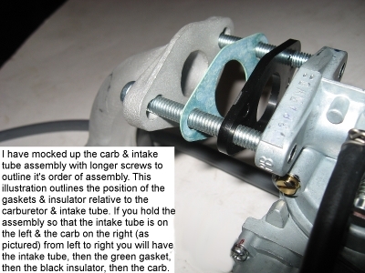
Then, install the carburetor, making sure that the gasket that lives in between the intake pipe & the cylinder head is in place.
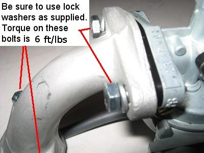
Do not overtighten the bolts that hold the two 6mm thread/10mm head intake pipe mounting bolts. The specification is 6 foot lbs.
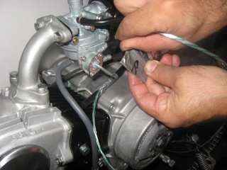
Now that the carburetor is installed, you can hook up the lines. It’s advisable to use a bit of grease on the connections in case you screw up & have to get them off.
You will notice in this photo that i am attaching the reserve line to the TOP hose connection point on the carb. This is the way it needs to be. The top connection point on the carb has a very small “R” embossed at the base of it. “R” is for reserve, which is the line with the aforementioned flag on it.
Just hook the other line to the other connection. That one is also marked. You will notice a very small “O” embossed at the base. “O” is for on.
Just pull the tape off at this point. It should tear relatively easy.
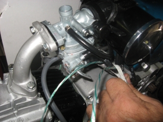
This is the atmospheric line. It does not connect to anything. Simply tuck it away under the choke lever & behind the fuel lines along the same route into the frame rail cavity.
Here is where your atmospheric line should wind up.
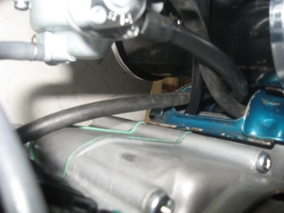
Another shot of the atmospheric line & fuel lines.
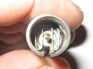
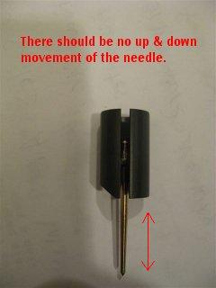
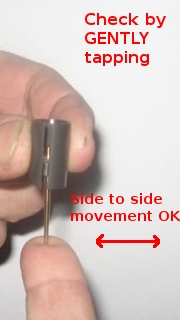
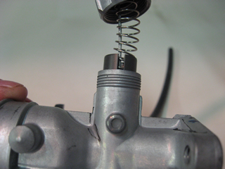
This is the “W” clip that lives down in the throttle slide. If you ever take the needle out & can’t figure out how it goes back in, this is the way. It must be all the way down in the slide or the needle will have up & down movement. To make sure that you have it all the way down, give the pointy end of the needle a VERY light tap. It should not come up at all. It will wobble a bit & that’s normal, but it should not come up at all.
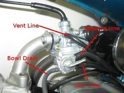
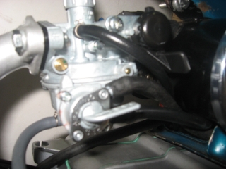
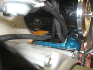
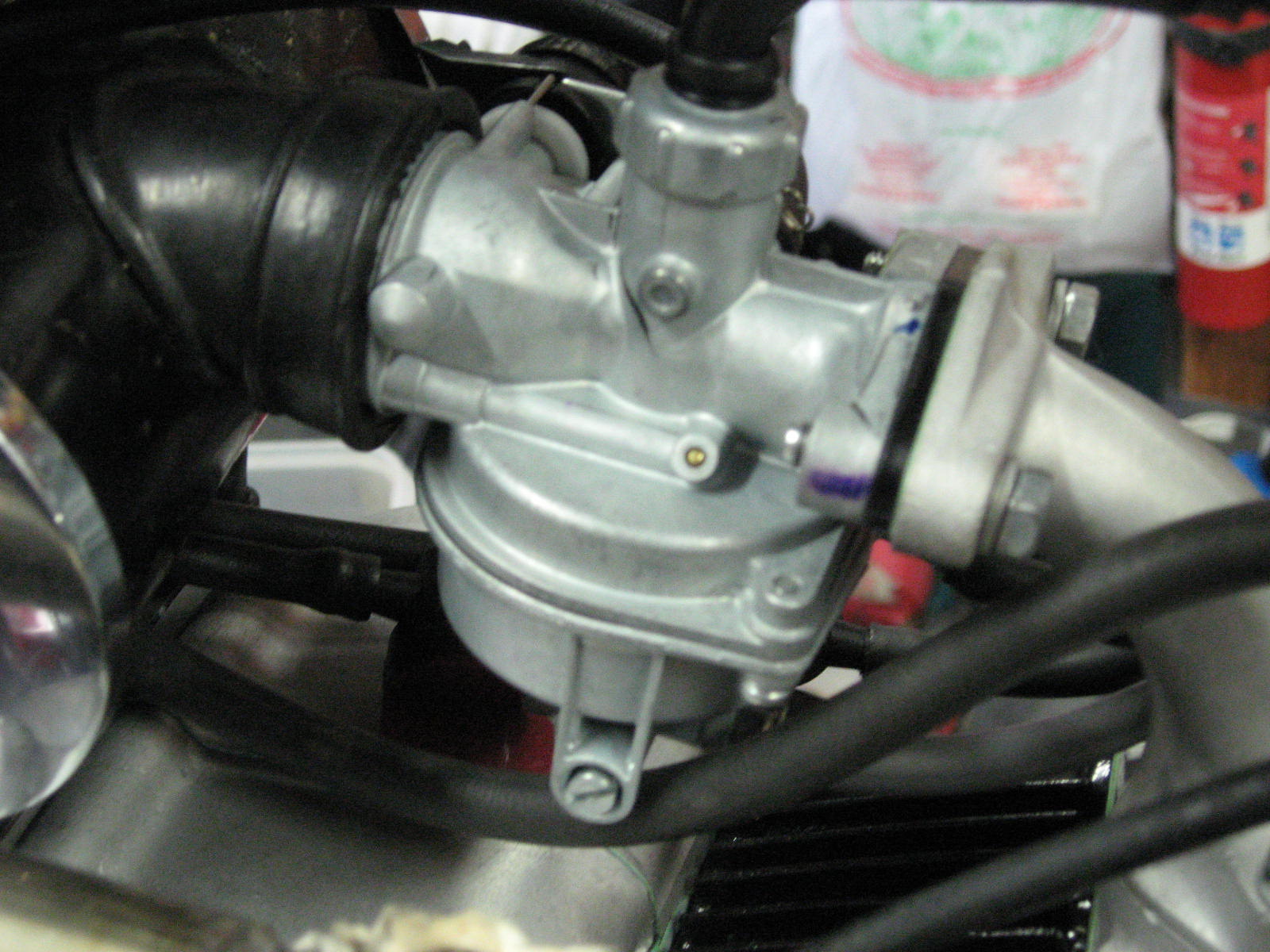
The photo above shows the orientation of the fuel lines, carburetor vent lines & the carb bowl drain.
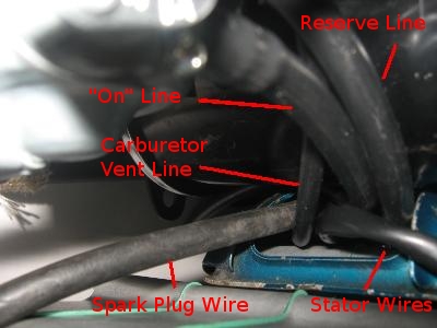
The photo above shows the view of the area under the air cleaner. Both fuel lines, the spark plug wire & the stator wires all run to this location. If you have one of my CT70 carb kits, the additional carburetor vent line runs here as well.
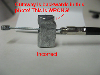
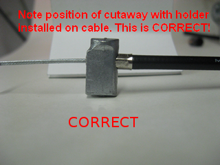
Cable End
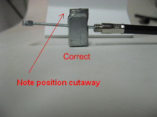
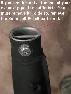
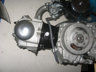
For 82cc Power up kits Remove Intake Snout As Shown Below. All others, intake snout must remain as standard.
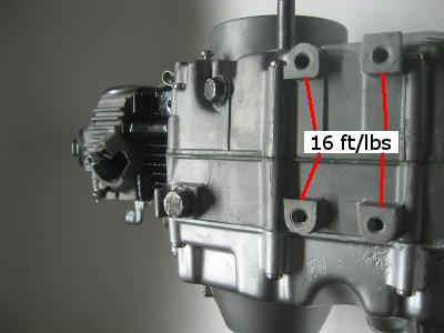
 The photo below depicts the four 8mm thread bosses where your footpeg/step bar mounts. I have cleaned these threaded bosses by running a thread cutting tap through all of them. I have torque tested these bosses/threaded holes to withstand the standard torque specification of 16 foot lbs. You must torque these bolts to 16 foot pounds. Make sure that the threads on the bolts you are installing are in good shape & can be turned in by hand. The more force you need to use to install these bolts into the engine by hand, the higher the chances are that you will damage the threads in the bosses & repairing them at your end will prove costly & time consuming. If you damage the threads on the engine by installing bolts with deformed threads or simply by overtightening them, you are responsible for the repair of those threaded bosses. The original bolts in this part of the engine were prone to loosening & if not periodically tightened by the owner, the threads would become marred from the loose footpeg bar banging into the backed out threads on the bolts. Then, if the owner tried to tighten the bolts, he was damaging the threads in the bosses by forcing the mangled bolt through the aluminum threads. I have assured that threaded bosses on the engine are in good shape & I may have performed a heli- coil thread repair on one or more of them. Installing those old bolts is ok, but if the threads are marred or if they thread in by hand but still feel loose from side to side once in, they will damage the threaded holes & could potentially start the process described above. Be sure you use good bolts with good, clean threads. Buy new ones if you feel there is any risk. Do not over or under torque these bolts. Consider for a minute that these 4 bolts support the riders weight entirely when the rider stands up. Think of what kind of load the bolts & threaded holes are subjected to when a heavier rider stands up & lands off even a small jump or obstacle. These bolts/threaded bosses don’t have an easy life & a lot is expected from them to keep the rider safe. If you don’t have a local source for 20mm & 25mm long, 8×1.25mm threaded bolts & necessary washers & you would like to buy some, you can get them in a simple kit form here: http://dratv.stores.yahoo.net/mabrpe.html Here is a helpful diagram in which you can see the orientation of the bolt, lock washer & flat washer arrangement in the link here http://ep.yimg.com/ca/I/dratv_2243_83507816 A strong word of caution: If you use too long a bolt in any given hole you could pierce through the aluminum casting in the engine, causing catastrophic damage, letting out all of the oil & needing complete engine disassembly to weld end repair. If you use too short a bolt in any given hole, you could rip out the threads because there is not enough purchase available. Pay particular attention to what size bolts go where using the above link to the diagram as well as the following description: The forward two footpeg bolts are the longer 25mm variety, but they get both lock washers AND flat washers. The rear two footpeg bolts are the shorter 20mm variety, & they only get lock washers.
To assure that the bolts won’t loosen in the future, use some TEMPORARY (not permanent) thread locking agent (I.E. Permatex Loctite 242/”blue” or equivalent temporary/removable thread locking agent) on properly torqued bolts with good threads. This will assure that what you put in will stay in place & never cause an issue. Here is an on line source for Loctite in case you are far from a source.
http://www.denniskirk.com/jsp/product_catalog/Product.jspskuId=3120&store=&catId=&productId=p3120&leafCatId=&mmyId= Thread locking agent is available at any auto parts store.
Another helpful point that i have found through the years is the installed position of the kickstart lever.

Break In:
Very important: Please trust my 30 plus years in the industry so i can allow this portion of the recommendation to be as brief as possible.
The old theory that an engine needs to be babied during it’s first 100 hours was thought up by corporate lawyers in an attempt to keep the operators of new machines safe simply by recommending that you go painfully slow on the initial rides so you had less of a likelihood to injure yourself, in turn reducing the number of lawsuits that the manufacturer of the bike would have to deal with. Those manufacturer recommendations are essentially urban legend at this point. How do racing teams with million dollar budgets break their engines in? Do they install them in road-going vehicles for 100 hours of gentle use before going to red line? Of course not. They break them in within a couple of days employing a method of three 20 minute runs of varying RPM’s, varying loads & having a critical cool down period between each run. Racing teams have the luxury of a breaking their engines in on a dyno (dynamometer), or “rolling road” where the engine is in the vehicle, running in place with a nice load on the engine & huge cooling fans. We can mimick that exact scenario. If you abide by the break in recommendations below, the engine will have superior piston ring sealing compared to an engine broken in by employing the manufacturer recommended method originally. It will run better, have more power & last longer.
Before starting the break -in period, assure the oil level & type is correct before starting the engine.
Once running, always switch the choke off as soon as possible. Never ride with the choke on.
Always wait until the cylinder head is warm to the touch before riding the bike. Allow the engine to be cooled by getting a steady flow of air over the cooling fins.
What NOT to do during the break in period:
- If you baby the engine during break in, the cylinder builds up a glaze that the piston rings will not be able to cut through until the first time the engine is brought to redline, at which time the glaze will be cut through violently, losing a good percentage of precious ring seal & decreasing performance. We don’t want that glaze to ever form. We want to cut through it continuously from the beginning by keeping a nice varying load with varying RPM’s on the engine & the aforementioned cooling periods which help seal the rings. Don’t baby the engine.
- Once warm, never allow a newly built engine to sit at idle for more than a minute or two, max, especially an air cooled one.
- Never lug the engine during the break in period.
- Never scream the engine higher than the recommended RPM’s for the initial break in runs outlined below.
- Never scream the engine with no load on it during the break in period.
- Never scream the engine when cold, ever.
During the break in period, vary the load. Run through the gears, accelerating briskly & slowing before downshifting.
Below is a break in schedule:
1) First run: Vary load. Do not lug. Do not over rev or rev high with no load. Run RPM’s to about 1/2 of available about 8-10 times. Run for 20 minutes. Shut off.
2) Allow engine to completely cool overnight. (This is a VERY important detail & the most important of all)
3) Change the oil prior to the next run (whether you change the oil when the engine is hot before the above cool down period or cold after the above cool down period, it matters not).
4) Second run: Same as first, but allow RPM’s to go to about 3/4 of available about 8-10 times.
5) Allow engine to completely cool overnight.
6) Third Run: Same as first & second, but gradually run RPM’s up to maximum a couple times on this run. Don’t sustain max RPM, but just attain it a couple times.
7) Allow engine to cool completely overnight.
8 ) Once the engine has gone through it’s third heat cycle, it’s broken in.
9) Fourth Run: Same as third run, but change the oil again before the next run.
At this point, the engine is fully broken in with fresh oil & all of the mating surface by-products flushed from the oiling system.
The bike can be operated as normal.